Antonie van Leeuwenhoek was a wealthy cloth merchant who lived in the city of Delft, in the Netherlands, from 1632 to 1723. He is best known for his pioneering work on microscopy: from 1673 onwards he created as many as 500 microscopes and from these made numerous significant discoveries. This included determining the existence of single-celled organisms, a discovery that ironically brought his scientific credibility into question for some time.
The success of these microscopes can be attributed to many things, but a number of technical matters stand out. First, his microscopes relied on a single lens. Compound microscopes (those with more than one lens in the light path) theoretically provide better resolution, but they are also much more technically challenging to fabricate. As well, Leeuwenhoek devised a relatively simple means to produce his single lens. In particular, his methodology appears to have reduced the need for precise grinding techniques, and grinding was a laborious and technically difficult process.
The few examples of Leeuwenhoek’s microscopes that remain today are elegant creations of brass or silver with many working parts. Although much less complex than modern microscopes, replicas of metal with the same working features are challenging to build and require some skill with a small number of tools (Figure 1-1). However, the basic functional aspects of the design and lens production can be replicated in a few minutes, using a few simple raw ingredients.
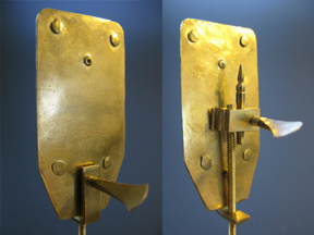 Figure 1-1. Front and back views of a brass replica of a van Leeuwenhoek microscope. Building such a replica requires a few tools and some skill with them, but below are instructions for building a microscope out of simpler materials, with the same optics and similar operating principles.
Following the steps available here, you will be able to construct a working microscope using van Leeuwenhoek’s general design and method of lens production. From this, you can then measure the size of the lens you make, and calculate its magnification. Lenses capable of 100X to 200X magnification are not too difficult to produce, and this article will also suggest and illustrate a number of interesting samples one can examine.
It’s amazing to consider how we often take microscopy for granted in this day and age. However, when you use the microscope you build yourself, try to imagine what it must have been like to peer through one of these creations and discover a completely unknown realm of life, because your instrument will reproduce the microbial world as it would have looked like using the technology of the seventeenth century.
The purpose of this guide is not to create a working replica of a Leeuwenhoek microscope. There are already detailed instructions available on this, in particular I recommend Alan Shinn’s instructions (see below). However, in the process of building such a replica from original documents, it became clear that it would be possible to create a microscope of similar design and power using only inexpensive materials that were easy to work with, and almost no tools. In a class environment this process has been successful with high school students as well as advanced undergraduates.
For further information on making more realistic replicas of Leeuwenhoek microscopes there are several sources, and I particularly recommend Alan Shinn’s site. For additional information on creating various types of lenses, see Baker, RC 1991 Science PROBE (April) pp. 53-62. For the method described below to calculate the power of the lens, see part 4 of John Davis’ article. All of these contain numerous other references of interest.
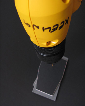 Figure 1-2. Drill a light path in both cardstock and posterboard at the same time using a 1/16 (or smaller if you have one) bit.
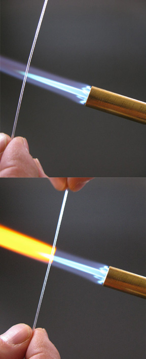 Figure 1-3. To stretch the glass, first place it in the flame, rolling it to heat it evenly until it is quite soft and wobbly.
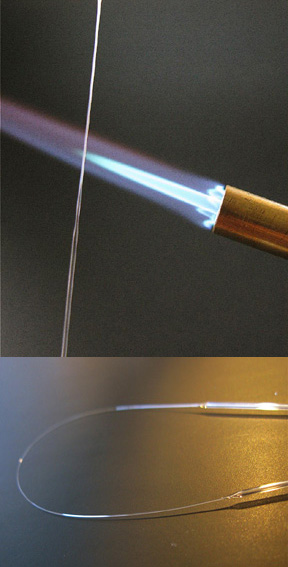 Figure 1-4. Once the glass is thoroughly soft, remove it from the flame and immediately pull apart the two ends so the softened part is stretched to a uniformly thin filament or tube.
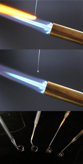 Figure 1-5. Break the stretched glass in the centre, the slowly feed one end of the thin portion into the flame (preferably a horizontal flame). As it heats, the tube will melt to a filament and a small ball will form at the end of the filament (upper panel). Once you are happy with the size of the ball remove it (bottom left). These are easy to make, so make several and chose the best sphere with no visible imperfections (like bubbles). Snap off the sphere leaving a short length of tube attached to it.
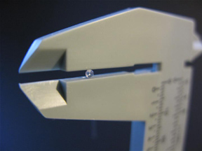 Figure 2-1. Measure the diameter of the lens using a micrometer.
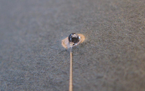 Figure 1-6. Place the lens in the hole on the inside of the posterboard, laying the remaining tube flat on the surface.
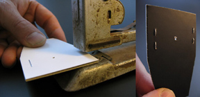 Figure 1-7. Staple the two pieces of paper together with the lens between them, and your microscope is assembled.
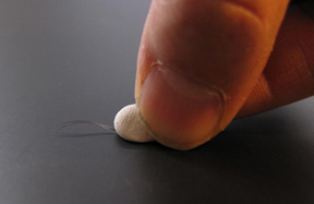 Figure 1-8. Take a pea size piece of tacky putty and press it on the subject (a feather barb is shown). The subject should stick to the putty when you remove it from the surface.
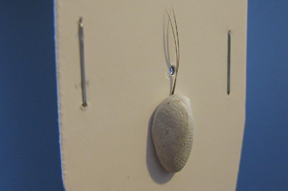 Figure 1-9. Press the putty with subject attached to the cardstock (thin) side of the microscope with the subject laying over the lens.
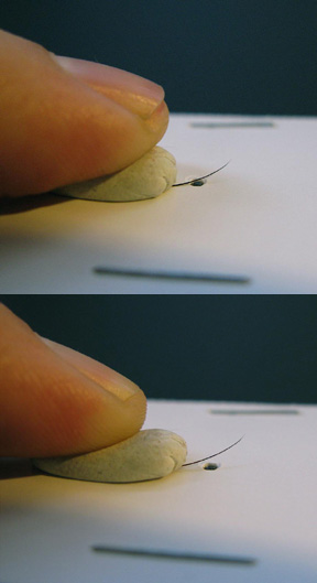 Figure 1-10. To focus, place your thumb on the putty. Pushing up will pivot the sample towards the lens, while pulling down will pull the sample away from the lens.
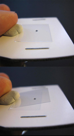 Figure 1-11. To view a liquid sample, follow the procedure of Figures 1-8 to 1-10 using a glass cover slip, and once attached to the microscope, drop the liquid sample on to the glass.
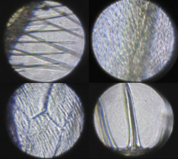 Figure 1-12. Clockwise from lower left these are a vein of an insect wing, the hairs on the trailing edge of an insect wing, cells in an onion skin, and the spikes on the surface of a radiolarian skeleton.
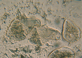 Figure 1-13. A example of an image with a lower magnification lens of live cells in liquid on a cover glass. This is the hypermastigote parabasalian Trichonympha from the hindgut of the termite Zootermopsis angusticolis.
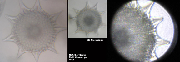 Figure 1-14. Comparison of the same Radiolarian skeleton with three different microscopes. At left is a commercial McArthur-Cooke field microscope set at 400X. In the centre is the same skeleton photographed with the same camera (a Canon Elph) and at the same scale (showing the power of this lens to be about 200X). On the right is the same sample again but photographed using the Canon G9 and a different microscope with a much higher power lens.
Figure 2-1. Measure the diameter of the lens using a micrometer.
Figure 1-14. Comparison of the same Radiolarian skeleton with three different microscopes. At left is a commercial McArthur-Cooke field microscope set at 400X. In the centre is the same skeleton photographed with the same camera (a Canon Elph) and at the same scale (showing the power of this lens to be about 200X). On the right is the same sample again but photographed using the Canon G9 and a different microscope with a much higher power lens.
Figure 2-1. Measure the diameter of the lens using a micrometer.
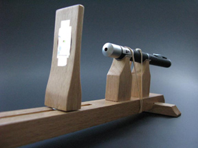 Figure 2-2. The basic set up for a stand to measure the power of a lens using a laser.
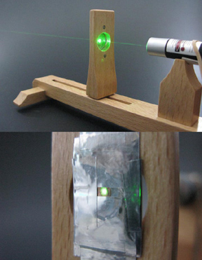 Figure 2-3. Align the laser so that the beam passes through the centre of the EM grid.
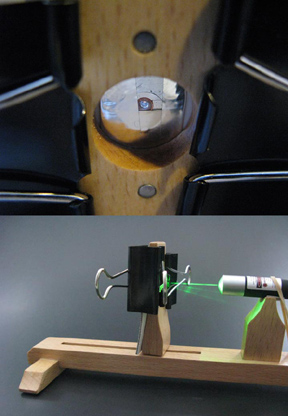 Figure 2-4. When the beam is centred, clamp the microscope onto the far side of the EM grid, so that the lens is directly behind the grid.
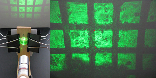 Figure 2-5. Turn on the laser, and the beam will pass though the grid, then the lens, projecting a magnified image of the grid onto a surface. Measure the distance between two points on this projected image (where the actual size on the grid is known), and measure the distance from the lens to the surface. For example, measure between the positions indicated by two red dots, which are 0.204mm apart on the actual grid. From these values using the equations given, the power of the lens can be calculated.